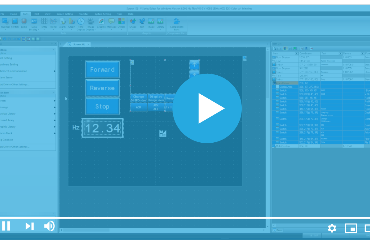
Alarming is one of the most crucial functions an HMI performs, enabling easier troubleshooting, preventative maintenance, and a focus on machine health. Alarming on a Monitouch V Series HMI has an incredible depth of functionality, from code execution to emailing detailed reports. In this blog, we will be covering the basics of setting up an alarm and informing the user.
For demonstration purposes, we will upload an existing application from an HMI and modify it.
Once uploaded, head over to the System Settings and select Alarm Server.
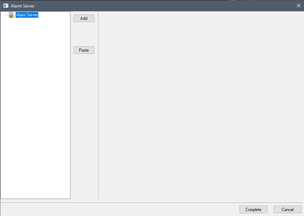
Next, click Add, then Complete to add an Alarm Block.
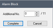
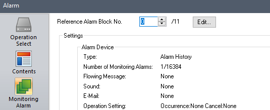
After clicking Complete, you should see a similar “Alarm Block” page as shown below.
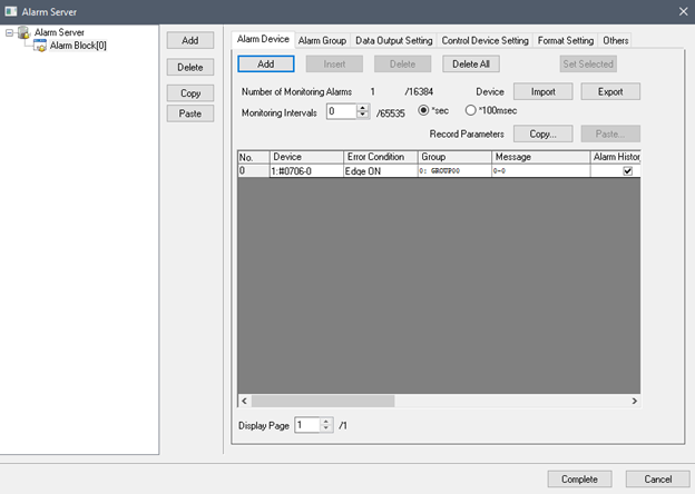
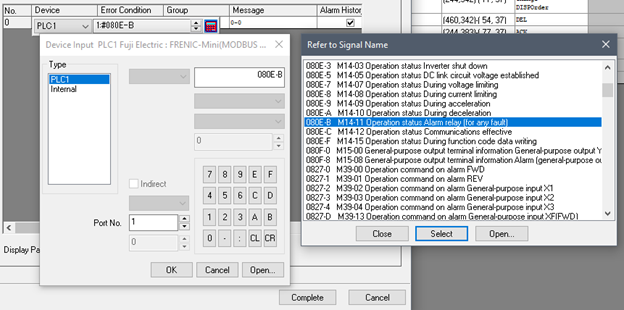
Now we’re going to change the alarm address to 080E-B for any alarm fault.
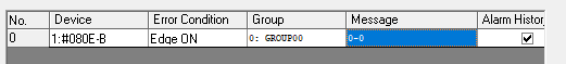
For the alarm messages, we will use the parameter feature to pull the alarm code integer from the VFD in and present the correct alarm message. Start by opening the message block editor. To do that, double-click on the message portion of the Alarm entry shown in the snippet below.
Next, click the Edit button.
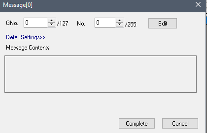
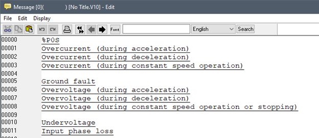
The Message Block 0 window should pop up. Copy and paste the following short list of alarm codes into Message Block 0, as shown in the below snippet.
%P0S
Overcurrent (during acceleration)
Overcurrent (during deceleration)
Overcurrent (during constant speed operation)
Ground fault
Overvoltage (during acceleration)
Overvoltage (during deceleration)
Overvoltage (during constant speed operation or stopping)
Undervoltage
Input phase loss
Keep the empty lines between each block of code.
The %P0S entry is Parameter 1, which we will now set up. Scroll to the far right of the Alarm Menu to locate the Parameter field.
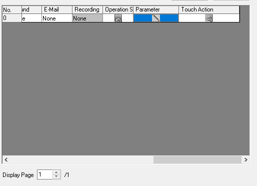
Double-click the Parameter Column to open the Parameter Table Editor shown below.
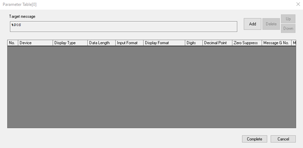
Next, click Add, set the Device Address to 0810, and the Display Type to Message No.

This will then pull the Message Table and populate parameter 0 when an alarm occurs.
To display alarms, we want to place an Alarm Part down. Navigate to your preferred screen number for alarms. Select Parts, then Alarm, and finally Alarm History. Place the Alarm Part on the screen and resize it to your liking.
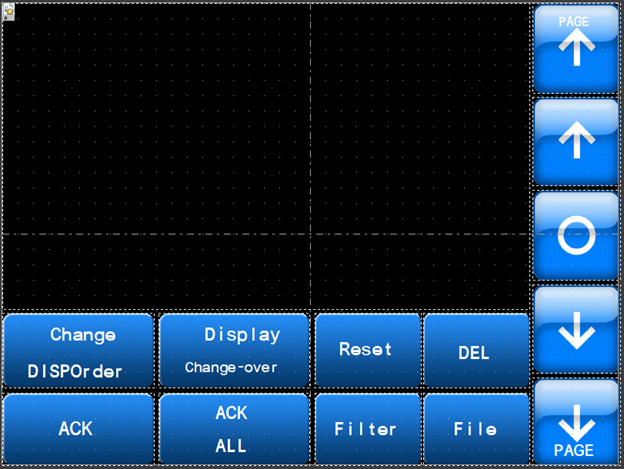
All the individual parts can be removed and customized to your liking, but that is beyond the scope of what we’re covering within this article. If you need further guidance in that area, contact us anytime – the Live Automation team is here to help.
In the meantime, let’s continue on. By default, the Reference Alarm Block No. should be set to zero (0).
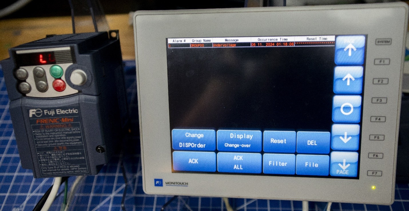
Now, let’s see it in action as we transfer the application to a V10 HMI, and simulate a low-voltage condition on the VFD.
Thank you for reading our blog. To learn more and stay up to date on critical technology integration processes, click the subscribe button above and stay tuned for more blogs coming your way soon. Don’t forget to follow Live Automation on social media too for even more technical content and industry insights.
Want to watch this process on video? Check it out on YouTube: Mastering Alarm Setup on a Fuji Monitouch V10 Series HMI